On a recent trip to England, I was intrigued as a friend casually showed me his smart meter. It wasn't a big electricity meter, it was just a little display visualising his electricity usage. I assume the actual heavy duty electrical stuff was somewhere else, and I would imagine that he doesn't have to manually read his meter and send in the number like we do here, or let someone in to read it like my parents used to do years ago.
This got me wondering about whether we could get a smart meter. This is not so easy or cheap in Germany (you have to either be a big consumer or find a meter-provider or electricity provider who does them) so then I wondered if our electricity meter, which is fairly new and digital, could be made "smart". On closer inspection, it actually claims to be smart. The smartness, from a user perspective though, seems to end with it having a digital display.
There is an entertaining video about the German effort to install so-called digital meters here (in German).
Fortunately, we don't have to get a PIN from our electricity network provider or provide it via torchlight to proceed, but that didn't mean it was going to be plain sailing either.
It became clear fairly quickly, that the meter has an Infra-Red (IR) interface for exchanging data. The window for this has a magnetic ring so that you can easily and even permanently attach a transceiver. There are lots of eBay sellers happy to sell you one. However, one seller in particular offers to build you a fuller solution including forwarding the data if you tell him the meter type. I owe this guy a lot of thanks for exchanging a lot of messages with me even though it didn't lead to a sale. We established with some simple debugging (e.g., holding a phone camera up to the IR-window), that this meter did not by itself output the data. It would need something to tell it to send data. Furthermore, there were hints out there that the IR LED might be very weak. This put me off a self-built Arduino solution, I wanted to be able to experiment easily, so went for this USB transceiver so I could easily test with a Linux laptop.
Here you can see it attached to the meter:
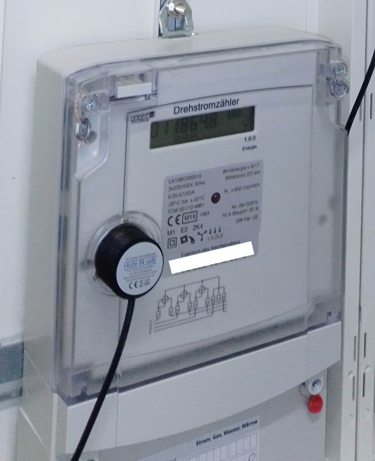
The general problem at first was that not many people seem to have this meter
(Logarex LK13BD), and there
is a fancier version (Logarex LK13BE) that is quite different. I also have the suspicion that
the same meter might come set up in different ways. In the end, I found the right
sequence of commands in the comments thread
of an article from someone working
with the same meter. My huge thanks to the author of that blog post
because it was evidence that this could be done and also contained (combined with the comment)
the crucial information needed to get going.
I was pretty beside myself with excitement when
cat /dev/ttyUSB0 finally yielded some content:
/LOG4LK13BD202015

000

C.1.0(06135975)

0.0.0(001LOG0006135975)

F.F(0000)

1.8.0(011788.687*kWh)

C.7.1(00000000)

C.7.2(00000000)

C.7.3(00000000)

0.2.1(ver.02, 150228, 671A)

C.2.1(1601130840)

C.2.9(1601130840)
To summarise that part, you need this command to set up:
stty -F /dev/ttyUSB0 300 -parodd cs7 -cstopb parenb -ixoff -crtscts -hupcl -ixon -opost -onlcr -isig -icanon -iexten -echo -echoe -echoctl -echoke
This command in a terminal to sit and listen:
cat /dev/ttyUSB0
And these commands (doing the second one quickly right after the first) to tell the meter to output data:
echo -n -e '\x2F\x3F\x21\x0D\x0A' > /dev/ttyUSB0
echo -n -e '\x06\x30\x30\x30\x0D\x0A' > /dev/ttyUSB0
And it's probably easiest if you do all of this as root (sudo su -)
I had also been trying to get the data to go into some nice web interface and at first tried ioBroker along the lines of this post. It had limited options though and I didn't get it to work. What looked more hopeful was the Volkszähler ("people's meter", in English) project as the sample configuration file from this webpage for their logger component had the same serial commands. I couldn't get the logger part (VZLogger) up and running on a modern Ubuntu, but also didn't try hard, as Volkszähler have a Raspberry PI image for the whole set up and it was clear that was going to be the solution. So for now I assumed this would work and had to deal with the next issue, how to get the data, or rather how to power and communicate with a Raspi two floors down in the basement.
Fortunately we have a cable that goes down there, originally intended as a phone line (we don't have a proper phone line, we have a cable internet provider that does phone via the modem). We had it extended to the part of the basement that's ours at the time the place was being finished. So the goal was to break this connection in the middle and use the connection and in addition put power over ethernet (PoE) to power the Raspi. There are power sockets down there, but they get paid for by everyone, and that wouldn't be fair. Very fortunately, the two sides of the cable were already in two halves and sitting joined in a little junction box that was more or less perfectly positioned for adding the Raspi with the USB transceiver.
First a step back. Ethernet over a phone cable that isn't even really proper twisted pair? Well, that does work as long as you have four cores and if you throttle the connection down to 10MBps. Equipment will not figure that out for you, you need to insert something that will only speak 10MBps. Upstairs we have an old 10MBps hub which does the trick. Would PoE work over telephone cable? I ordered an injector (power + LAN on one side, LAN output on the other side) from eBay and a separator (LAN in one side, 5V USB Micro plug plus LAN RJ45 plug on the other side) for the Raspi. A quick test showed that this also worked.
We already had a Raspi lying around, which needed a MicroSD card. I made the mistake of buying one
that is too big at first, so had to swap it with the one in my phone which was also a bit
on the small side. Getting the Volkszähler image
written to the SD card using a Mac was also not easy
but worked out with
ApplePi-Baker (v1.x version!)
in the end. I changed the /etc/vzlogger.conf file to have the
sample configuration
from this webpage.
Because we wanted the ethernet connection to still be carried back out
to the other room in the basement, I attached a USB ethernet port and had to look up
how to do bridging
(here)
and configuring the speeds etc. on ethernet ports (more on that below).
Upstairs, away from telephone cable, everything seemed to work well, except I didn't know yet if the
VZLogger part would work.
It was finally time to install the stuff for real. Crimping RJ45 connectors on telephone cable is a real pain, and in the end I attached an existing connector with thinner wire on to one half which had cores that were basically too thick to go into an RJ45 plug.
The initial setup worked immediately as far as the meter reading, communication and power was concerned. The only troublesome parts were figuring out the "resolution" parameter for the Volkszähler channel (turns out it should just be 1, as the meter reads in kWh) and getting the ethernet bridge to work. This may or may not have had something to do with the not-well-crimped cable, or it may have just been bad configuration. In any case, after checking things over using a nice article on bridge debugging it seemed the Linux-Bridge part was OK. There was some connection (flashing lights) happening but no traffic possible. In the end what seemed to work was to set the ethernet ports to both be at 10MBps (already done before in the intial setup) with no autonegotiation on the half that went up to the hub upstairs and with autonegotiation ON on thw half that continued to the other room in the basement. And both ports set to FULL duplex and not half. You can do this with ethtool (helpful guide here):
sudo ethtool -s eth0 autoneg off speed 10 duplex full
sudo ethtool -s eth1 autoneg on speed 10 duplex full
And preserve it all in etc/network/interfaces like this
(helpful link here,
together with the article on
bridging
above):
auto lo
iface lo inet loopback

auto eth0
iface eth0 inet manual

auto eth1
iface eth1 inet manual

auto br0
   iface br0 inet dhcp
   bridge_ports eth0 eth1
   post-up /sbin/ethtool -s eth0 autoneg off speed 10 duplex full
   post-up /sbin/ethtool -s eth1 autoneg on speed 10 duplex full
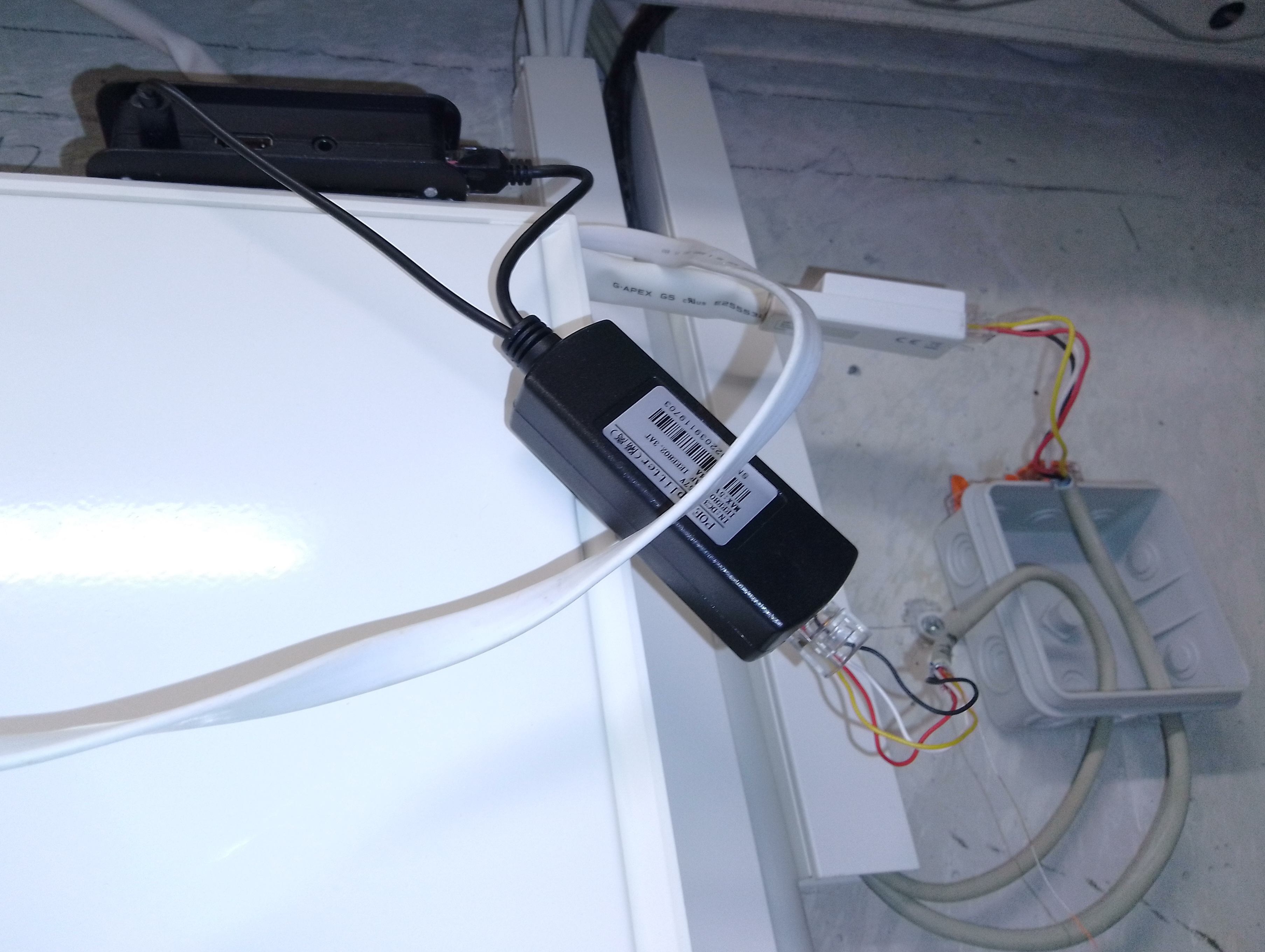
Here's a photo of the cabling before adjustments and cleaning up:
And here's a screenshot showing our electricity usage!
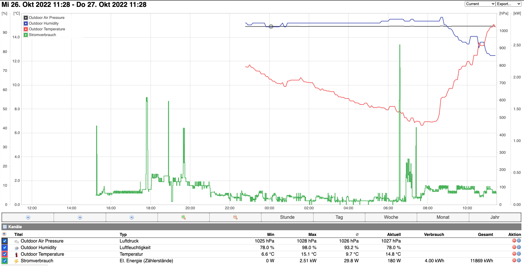
For extra fun, I followed these instructions to add outdoor temperature, humidity and air pressure curves. I've given Birgit the job of building an indoor temperature/humidity monitor using an old Arduino-style-with-WiFi board we have. I'd love to see if we can get our water/warm water/heating consumption measured in realtime somehow as well.